NABU expansion cards
The NABU has four internal expansion slots, which allow extra hardware to be added.
Expansion cards which were available from NABU:
- Floppy disc controller (WD1797)
- Hard disc controller (connects an external Western Digital 1001 controller to the NABU bus)
- The WD1001 bus is the 8-bit precursor to IDE/ATA, sometimes called XT-IDE or XTA (XT Attachment).
- Serial port
A standard NABU PC needs to have an Option Card fitted to allow expansion cards to be fitted. The Option Card converts the four independent NABU expansion ports into a single connector which daisy-chains from card to card. This makes the inside of the machine tidier, and reduces the total cable length and bus loading.
Port interface
The standard NABU PC expansion ports (motherboard J9 through J12) are wired as follows:
| Pin | Name | Function |
|---|---|---|
| 1 | JxINT | interrupt request (for this slot) |
| 2 | /OM1 | M1 output from Z80 CPU. Indicates instruction fetch and interrupt acknowledge. |
| 3 | O3.58 | 3.58MHz clock |
| 4 | JxAIN | audio input from expansion card (for this slot) |
| 5 | /CSx | chip select (for this slot) |
| 6 | OA0 | address bus LSB |
| 7 | OA1 | address bus bit 1 |
| 8 | OA2 | address bus bit 2 |
| 9 | OA3 | address bus bit 3 |
| 10 | O1.79 | 1.79MHz clock |
| 11 | /OWR | bus write cycle (from Z80) |
| 12 | /ORD | bus read cycle (from Z80) |
| 13 | /OIORQ | bus I/O request (from Z80) |
| 14 | /WAIT | wait state request (to Z80) |
| 15 | /RST | negative-going reset |
| 16 | OD0 | data bus LSB |
| 17 | OD1 | data bus bit 1 |
| 18 | OD2 | data bus bit 1 |
| 19 | OD3 | data bus bit 1 |
| 20 | OD4 | data bus bit 1 |
| 21 | OD5 | data bus bit 1 |
| 22 | OD6 | data bus bit 1 |
| 23 | OD7 | data bus MSB |
| 24 | +5V | +5V power supply |
| 25 | +5V | +5V power supply |
| 26 | GND | Ground |
| 27 | GND | Ground |
| 28 | GND | Ground |
| 29 | +12V | +12V power supply |
| 30 | -12V | -12V (negative) power supply |
Note: pins marked “(for this slot)” are specific to one connector. All pins without this designation are connected to the same-named pin on every slot.
Option card J9A pinout
The Option card combines the four motherboard expansion ports into a single 30-pin header which can be daisy-chained to all the I/O cards.
This improves the wiring inside (four long cables are replaced with four shorter daisy-chained cables) which in turn makes the machine easier to service, but also reduces the capacitive and inductive load the cable places on the system bus.
According to Vintagecomputer.ca, an 8K Version 2 ROM is required for the Option Card to work. This requires a small motherboard modification if a 4K (non-floppy) ROM was originally fitted.
The “option card” J9A output port (which connects to the first expansion card in the chain) is wired as follows:
| Pin | Name | Function |
|---|---|---|
| 1 | /RST | negative-going reset |
| 2 | /OM1 | M1 output from Z80 CPU. Indicates instruction fetch and interrupt acknowledge. |
| 3 | O3.58 | 3.58MHz clock |
| 4 | GND | system power supply ground |
| 5 | J9AIN | audio input from expansion card |
| 6 | OA0 | address bus LSB |
| 7 | OA1 | address bus bit 1 |
| 8 | OA2 | address bus bit 2 |
| 9 | OA3 | address bus bit 3 |
| 10 | GND | system power supply ground |
| 11 | /OWR | bus write cycle (from Z80) |
| 12 | /ORD | bus read cycle (from Z80) |
| 13 | /OIORQ | bus I/O request (from Z80) |
| 14 | /WAIT | wait state request (to Z80) |
| 15 | OD0 | data bus LSB |
| 16 | OD1 | data bus bit 1 |
| 17 | OD2 | data bus bit 1 |
| 18 | OD3 | data bus bit 1 |
| 19 | OD4 | data bus bit 1 |
| 20 | OD5 | data bus bit 1 |
| 21 | OD6 | data bus bit 1 |
| 22 | OD7 | data bus MSB |
| 23 | J9INT | interrupt request from first card |
| 24 | J10INT | interrupt request from second card |
| 25 | J11INT | interrupt request from third card |
| 26 | J12INT | interrupt request from fourth card |
| 27 | /CS0 | address decode/chip select for first card |
| 28 | /CS1 | address decode/chip select for second card |
| 29 | /CS2 | address decode/chip select for third card |
| 30 | /CS3 | address decode/chip select for fourth card |
Power connection
Power connector J16 carries the following voltages:
| Pin | Name | Function |
|---|---|---|
| 1 | GND | Ground |
| 2 | GND | Ground |
| 3 | -12V | -12V (negative) power supply |
| 4 | +5V | +5V power supply |
| 5 | +12V | +12V power supply |
I/O addresses
I/O cards are accessed at the following addresses:
| Card no. | Connector | I/O address MSN |
|---|---|---|
| 1 | J9 | Cx hex |
| 2 | J10 | Dx hex |
| 3 | J11 | Ex hex |
| 4 | J12 | Fx hex |
ID byte
Per (MacGyver75, I/O cards have an ID byte in the topmost address (CF, DF, EF or FF hex). This means cards may be in any slot, and the NABU will detect them automatically.
The following ID bytes are known:
| ID byte (hex) | Card type |
|---|---|
08 | NABU Serial port |
10 | NABU FD1797 floppy disk |
50 | NABU CompactFlash adapter v2 by Randomvariations |
E8 | NABU Winchester hard disk controller (Xebec) |
Bold entries are official NABU expansion cards.
Non-compliant cards which have no ID byte:
- IDE adapter by Gavin Tersteeg
Option card
The option card is required for connecting expansion cards to a NABU PC.
It combines the four ports on the NABU motherboard into a single port, which is then connected up to the first expansion card. Subsequent expansion cards daisy-chain off the previous one.
The motherboard slots have slot-specific interrupt and chip-select pins; the option card combines these into one slot, at the cost of losing the power supply pins.
Photos
Thanks to v1ph3rpunk on the NABU PC Discord for these.


Wiring diagram
Thanks to MacGyver65 on the NABU PC Discord for this.
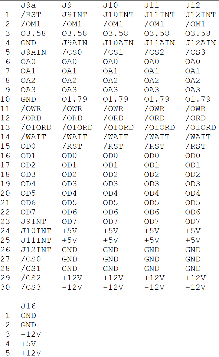
J9a is the pin header which connects to expansion cards.
J9 through J12 connect to the motherboard headers.
The audio outputs from cards 10 through 12 are not connected. This means only one card can output audio, unless the cards with sound output can be enabled and disabled.
Floppy disk controller
Hard disk controller
Serial port
 There may be inaccuracies in the serial port schematic, see this discussion on the Nabu PC Discord. R6 and R7 may be incorrect.