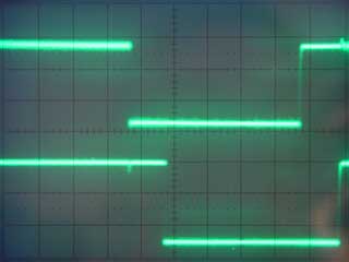
68008 Dartboard control pcb. By Lee Davison.
Back
This is the code that drives the I2C bus on th edart control board. The routine Getadrak is to allow access to the bus via the USR() function in EhBASIC.An example of it's use can be found here.
* I2C bus scan assembly code. * This code is fully relocatable so no ORG address is given * Once the code is loaded into memory it needs the user vector to be set to the * address of Getadrak. It is then called with USR(ad) where ad is the I2C bus * device address to test. The value returned is 0 for no ack, -1 for ack. URT_BASE EQU $80000 * UART base address URT_IP EQU URT_BASE+$1B * input port URT_OPbs EQU URT_BASE+$1D * output port set bit URT_OPbc EQU URT_BASE+$1F * output port clear bit * these values correct for version 1.10 of EhBASIC68 LAB_EVBY EQU $2536 * evaluate byte parameter, result in d0 LAB_24D5 EQU $2760 * normalise FAC1 FAC1_m EQU $40594 * FAC1 mantissa FAC1_e EQU $40598 * FAC1 exponent FAC1_s EQU $40599 * FAC1 sign * address device and get ack as true/false Getadrak BSR.s I2C_start * generate I2C start JSR LAB_EVBY * get byte parameter, result in d0 and Itemp BSR.s I2C_wrby * write I2C byte, returns /ack in d0 MOVE.w d0,FAC1_e * possibly clear exponent & sign BEQ.s LAB_noak * branch if there was no ack MOVE.w #$A080,FAC1_e * set exponent & sign for -1 LAB_noak MOVE.l d0,FAC1_m * save mantissa BSR.s I2C_stop * generate I2C stop JMP LAB_24D5 * normalise FAC1 & return * generate I2C start I2C_start BSR.s I2C_dast * set I2C data (UART op bit 7) BSR.s delay_01 * count 1 delay BSR.s I2C_ckst * set I2C clock (UART op bit 6) BSR.s delay_01 * count 1 delay BSR.s I2C_dacl * clear I2C data (UART op bit 7) BSR.s delay_01 * count 1 delay BSR.s I2C_ckcl * clear I2C clock (UART op bit 6) BRA.s delay_01 * count 1 delay * generate I2C stop I2C_stop BSR.s I2C_dacl * clear I2C data (UART op bit 7) BSR.s delay_01 * count 1 delay BSR.s I2C_ckst * set I2C clock (UART op bit 6) BSR.s delay_01 * count 1 delay BSR.s I2C_dast * set I2C data (UART op bit 7) * count 1 delay (approx 106 cycles) delay_01 MOVE.l d7,-(sp) * save d7 MOVE.l (sp)+,d7 * restore d7 MOVE.l d7,-(sp) * save d7 MOVE.l (sp)+,d7 * restore d7 RTS * set I2C clock bit (UART op bit 6) I2C_ckst MOVE.b #$40,URT_OPbs * set I2C clock (UART op bit 6) RTS * clear I2C data bit (UART op bit 7) I2C_dacl MOVE.b #$80,URT_OPbc * clear I2C data (UART op bit 7) RTS * set I2C data bit (UART op bit 7) I2C_dast MOVE.b #$80,URT_OPbs * set I2C data (UART op bit 7) RTS * clear I2C clock bit (UART op bit 6) I2C_ckcl MOVE.b #$40,URT_OPbc * clear I2C clock (UART op bit 6) RTS * wait for I2C clock bit to rise (UART ip bit 4) I2C_wccl BTST #4,URT_IP * read UART input port BEQ.s I2C_wccl * loop if clock bit low BRA.s delay_01 * now do delay * write I2C byte, returns /ack in d0 I2C_wrby MOVE.l d1,-(sp) * save d1 MOVEQ #7,d1 * eight (0 - 7) bits to do LAB_3172 BTST d1,d0 * test bit n of byte BEQ.s LAB_317E * branch if bit = 0 BSR.s I2C_dast * set I2C data (UART op bit 7) BRA.s LAB_3184 * skip clear LAB_317E BSR.s I2C_dacl * clear I2C data (UART op bit 7) LAB_3184 BSR.s delay_01 * count 1 delay BSR.s I2C_ckst * set I2C clock (UART op bit 6) BSR.s I2C_wccl * wait for I2C clock bit to rise BSR.s I2C_ckcl * clear I2C clock (UART op bit 6) BSR.s delay_01 * count 1 delay DBF d1,LAB_3172 * decrement bit count and loop until done BSR.s I2C_dast * set I2C data (UART op bit 7) BSR.s delay_01 * count 1 delay BSR.s I2C_ckst * set I2C clock (UART op bit 6) BSR.s I2C_wccl * wait for I2C clock bit to rise MOVEQ #0,d0 * clear sent byte BSR.s I2C_rdbi * read I2C data into d0 bit 0 BSR.s I2C_ckcl * clear I2C clock (UART op bit 6) BSR.s delay_01 * count 1 delay MOVE.l (sp)+,d1 * restore d1 BCHG #0,d0 * test and change ack I2C bit RTS * read I2C data into d0 bit 0 I2C_rdbi BTST #5,URT_IP * read UART input port BEQ.s LAB_3136 * branch if data bit low ADDQ.b #1,d0 * set bit 0 if I2C bit set LAB_3136 RTS
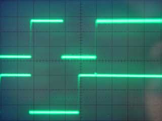
I2C Waveforms.