![[Return to top]](../../epc.png) 68008 Dartboard control pcb - I2C Bus. By Lee
Davison.
68008 Dartboard control pcb - I2C Bus. By Lee
Davison.
Back
68008 Dartboard control pcb - I2C Bus. By Lee
Davison.
Back
On the top right hand side of the board is a four pin connector labeled LED DISPLAYS and numbered as P4.
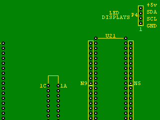
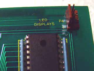
This connector was used as an I2C bus port and has the necessary open collector drivers and pull up resistors, all that's needed is some software.
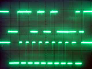
I2C Bus hardware.
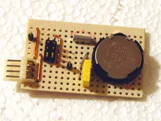
For the purpose of having something to drive a small board was made up with a RAMTROM FM30C256 'data collector' chip. This chip has 32k bytes of non volatile RAM, a real time clock, a reset generator (not used in this application) and a tamper detector input which is active even when the system is powered down.
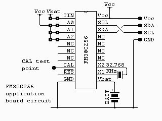
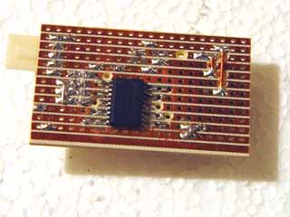
The board consists of the chip plus a 32768 Hz watch XTAL, a 3V lithium backup battery, connector for the I2C bus and a header for the selectable address and tamper inputs. There is also a test tag for ground and the calibration output.The whole lot fits on a piece of stripboard less than 2" by 1.4". The FM30C256, being a surface mount device, is mounted on the copper side of the board.
Software.
There are two demonstration programs, the first is an assembly program to allow you to interrogate the I2C bus from EhBASIC, the second is a short BASIC program that loads this code then uses it to interrogate all the I2C bus write addresses and display the results.
View assembly code. View EhBASIC code. Download both as a zip file. ![[Download]](../../zip_sm.png)
![[e-mail]](../../eml_sm.png)