![[Return to top]](../../epc.png) Z80 LED matrix. By Lee Davison.
Z80 LED matrix. By Lee Davison.
Back
![[Return to top]](../../epc.png) Z80 LED matrix. By Lee Davison.
Z80 LED matrix. By Lee Davison.
Back
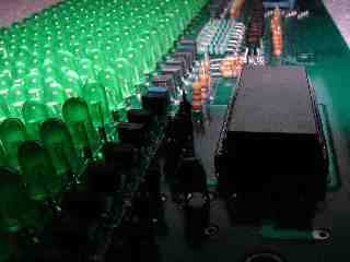
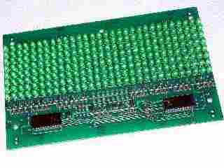
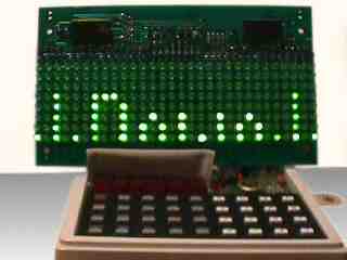
I bought a number of these display panels at a radio rally some time ago. They came without driver chips and were well worth the money even if half the LEDs didn't work. As it was most of the LEDs did work and one board was found with the drivers soldered on so I decided to try and get at least one board to do something.Hardware.
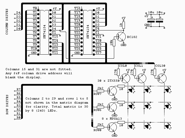
The two four to sixteen line decoders decode the D0 to D3 column addresses. D4, which is inverted by the BC182 for the second decoder, is used to select which decoder is active at any time. The outputs of these decoders, with the exeption of Y15 and Y31, drive the ZTX550 column transistors and hence the columns. Columns 15 and 31 are not fitted so addresses $0F and $1F effectively blank the display.Interface.The row drives, R0 to R7, activate the corresponding LEDs in the currently addressed column.
The matrix is connected to the Z80 PIO on the MicroProfessor I/O board as follows ..

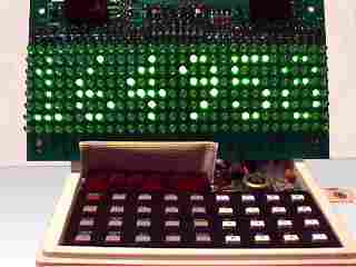
The software is basically just a demo of the sort of things that can be displayed. There is a display driver that reads out the bytes from a buffer and does one scan of the entire matrix. There are routines that can scroll the display up, down, left and right. Routines to make the display flash and also a routine that can do a 'random' bit by bit transition from one pattern to another.View the sourceWhile the code by itself isn't very practical it does include most of the routines that would be needed to make a usefull display driver.
.asm driver
![[e-mail]](../../eml_sm.png)