Table of Contents
Hobbymat MD65 lathe
An old but sturdy east-German (DDR/GDR) metalworking lathe. It was also sold with slight build variations as the following:
- Proxxon MD65
- Proxxon SD300
- Prazi MD65
- Prazi SD300
- SU300 Masterturn
Surprisingly enough it's still on sale –
- Eton e.K. supply spare parts
Manuals
I've scanned the manuals which came with my MD65.
- MD65 manual – scanned and cleaned up by myself.
- Some cheeky people have been printing this and selling copies on ebay… save yourself the money and download it here for free!
- This particular MD65 manual isn't branded Hobbymat on the front page. I'm not sure why this is!
- The original manual is about A5 sized, but this scan prints very well at A4 size.
- Chronos (?) tumbler reverse gear kit instructions
- See below for a partial copy of these
- I'm missing the third page which included some additional feed gear settings for coarser pitches.
- Please email philpem@gmail.com if you have a copy of the full manual, or type up the missing change-gear settings.
The following document came from the Hobbymat mailing list on Yahoo Groups 'back in the day'. I have it printed off at A4 size and keep it next to my lathe for easy reference.
Lathe tools guide
I don't know where I found this image, but it's another one I have in my quick reference booklet next to the lathe.
Headstock and tailstock tapers
- Headstock: MT2 (Morse Taper)
- Tailstock: MT1 (Morse Taper)
Drive belts
- MD65
- 8 x 425 mm
- 8 x 375 mm
- Essel Engineering slow-speed kit
- 6 x 335 mm
The above drive belts are (at the time of writing) available from:
-
- These are toothed on the rear and can be a bit fussy to get on and off the wheels.
- I've also seen other belts appear on eBay from a seller in Poland. These are a more solid design than the Optibelt ones sold by Heritage Lathes, and can be a little easier to get on and off the pulleys.
Upgrades
Tumbler reverse
I've got a partial set of the instructions for this – I'm missing the third page which contains the rest of the list of feeds and speeds. For convenience's sake, I've retyped the instructions here. Capitalisation and punctuation is as per the original document.
I believe this kit was originally sold by Chronos, but they no longer have any copies of the instructions.
This TUMBLER REVERSE GEAR ASSEMBLY has been developed to enhance the capabilities of the HOBBYMAT Type MD65 Precision Lathe and to dispense with the need to, reverse the Motor or, laboriously rewind the Saddle by hand at the end of a turning operation. Because it will now be possible to turn either Left or Right Hand, there will be a considerable saving of time.
Maintenance of the Assembly will be minimal, since the DELRIN GEARS, fitted with OILITE BEARINGS, run on HARDENED STEEL SPINDLES. A GREASE NIPPLE is fitted to facilitate lubrication of the LEADSCREW THRUST BEARING.
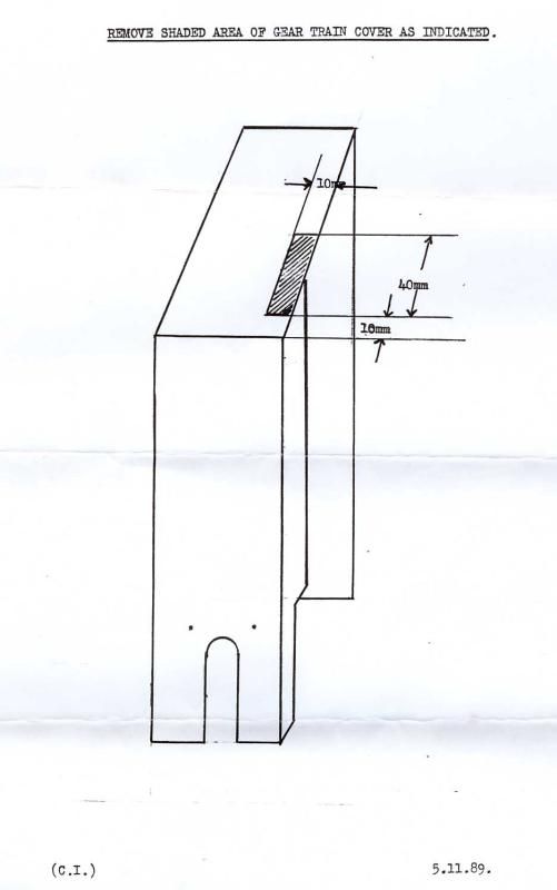
Installation of the ASSEMBLY is quite straightforward and does not require any modification to the basic Lathe, apart from forming a 50 mm X 10 mm slot in the Gear Cover to accommodate the Assembly Operating Lever. Please refer to MD65 Operating Instructions and Spare Parts List for identification of parts listed hereunder.
FITTING INSTRUCTIONS :-
- Remove Gear Train Cover
- Loosen M6 Bolt (Item 24 Page 10) and disengage Clutch from Coupling.
- Remove Coupling and Key together with Circlip (Items 11, 30 and 31 page 38).
- Loosen M8 Bolt and allow the Apron (Items 21 and 1 Page 48) to swing forward.
- Remove Countersunk Screw and Washer (Items 15 and 16) together with Twin Gear Assembly (Items 3, 4 and 5 page 48)
- Remove 100 T Gear and Key (Items 10 and 29 Page 38) from Leadscrew (Item 2 Page 38)
- Remove Apron (Item 1 Page 48).
- Fit Tumbler Reverse Gear Assembly.
- Refit 100 T Gear, Key and Circlip to Leadscrew.
- Refit Twin Gear Assembly complete with 1 X 20 T and 1 X 75 T Gear.
- Refit M4 Countersunk Screw and Washer
- Swing Apron to rear and engage the 75 T Gear with the 30 T Gear on the Headstock Mandrel, allowing the appropriate amount of backlash between the various Gears and tighten the M8 Bolt.
- Refit Coupling and Key.
- Engage Clutch with Actuating Arm and tighten the 6M Bolt.
The Clutch will not operate until the Tumbler Gear is engaged. The THREE POSITIONS are :- Lever TOWARDS the Operator for RIGHT to LEFT traverse, ie. normal operation, Lever AWAY from Operator for LEFT to RIGHT traverse. NEUTRAL is located MIDWAY between FORWARD and REVERSE.
TABLE OF FEEDS:-
| W | Z1 | Z2 | L | mm | ins. |
|---|---|---|---|---|---|
| 30 | 75 | 20 | 100 | .08mm | .003 Ins. |
| 35 | 70 | 20 | 100 | .1mm | .004 Ins. |
| 40 | 65 | 20 | 100 | .123mm | .005 Ins. |
| 50 | 55 | 20 | 100 | .18mm | .007 Ins. |
| 55 | 50 | 20 | 100 | .22mm | .008 Ins. |
| 60 | 45 | 20 | 100 | .26mm | .010 Ins. |
| 65 | 40 | 20 | 100 | .335mm | .013 Ins. |
| 70 | 35 | 20 | 100 | .4mm | .016 Ins. |
| 75 | 30 | 20 | 100 | .5mm | .020 Ins. |
(C.I.) 5.11.89.
Editor's note: The original document included a third sheet of paper with additional change gear / feed rate options which is missing. If you have a copy of this (or any other feed gear options you've calculated for the tumbler reverse), please contact me at the email address at the top of the page.